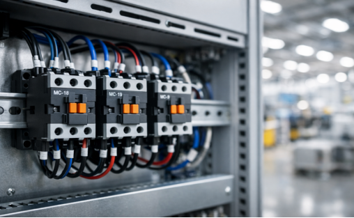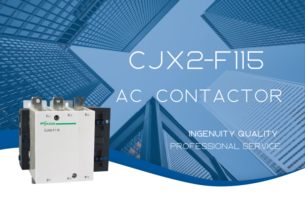
Industrial machines rely on 3 phase contactors as the crucial link between low-power control signals and high-power machinery. This guide covers what a 3-phase contactor is, how it works internally, where it’s used, and most importantly, how to select and install one correctly and safely.
What is a 3-phase Contactor?
A 3-phase contactor is an electrically controlled, heavy-duty switch built for industrial loads. Let’s break that down:
- Heavy-Duty Switch: Unlike a household light switch, a contactor handles immense loads — high voltages (480V or 690V) and high currents typical in industrial settings.
- Electrically Controlled: It’s operated remotely by a small electrical signal sent to its internal coil, making it ideal for automated systems controlled by PLCs or push-button stations.
- 3-Phase: Industrial equipment runs on 3-phase power — three alternating current lines. The contactor switches all three simultaneously for balanced power delivery.
Think of it as a powerful gatekeeper: a small signal opens the gates for a massive flow of power. When the signal stops, the gatekeeper closes, cutting power safely.
How Do Contactors Work?
A contactor’s internal components work together like the anatomy of a muscle. Here’s each part:
1. The Coil
The coil is an electromagnet — the heart of the control circuit. Applying control voltage (24V DC, 120V AC, or 220V AC) generates a magnetic field that initiates switching.
2. The Armature and Core
The core is stationary; the armature moves. When energized, the magnetic field pulls the armature toward the core. This physical movement is what makes the contactor switch.
3. The Main Contacts (Poles)
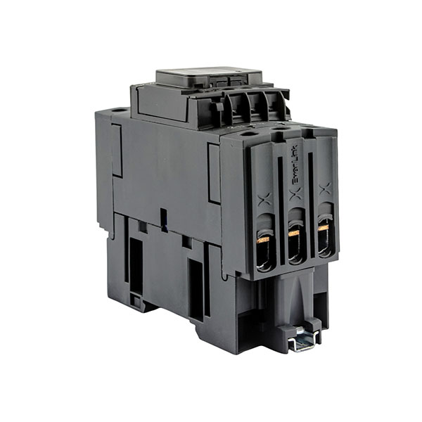
Heavy-duty copper or silver alloy contacts carry the main power to the load. In a 3-phase contactor, there are three sets — labeled L1/T1, L2/T2, L3/T3 — that are Normally Open (NO) at rest. When the armature moves, they close and complete the circuit.
4. The Auxiliary Contacts
Smaller contacts on the same armature handle low-power signals for logic and status indication:
- Normally Open (NO): Closed when energized — perfect for a “Motor Running” indicator light.
- Normally Closed (NC): Open when energized — ideal for “Motor Stopped” lights or safety interlocks.
Many contactors, like the popular WTAIDQ CJX2D series, include one NO and one NC auxiliary contact built-in (1NO+1NC).
5. The Springs
When coil voltage drops, the magnetic field collapses. Springs push the armature back to its resting position, instantly opening the main contacts and shutting off the load.
6. The Enclosure
The protective plastic housing insulates live parts, shields internal components from dust and moisture, and helps suppress the electric arc during high-current switching.
The Working Principle in Action
Here’s a complete cycle — all happening in milliseconds, designed to repeat millions of times:
1. De-energized State (OFF)
- No voltage at coil terminals A1 and A2.
- Springs hold the armature away from the core.
- Three main contacts (L1/T1, L2/T2, L3/T3) are open — no power flows to the motor.
2. Energizing State (ON)
- A control signal sends voltage to the coil terminals.
- The magnetic field overcomes spring force and pulls the armature in with a distinct “clunk.”
- All three main contacts close simultaneously — power flows through L1/T1, L2/T2, L3/T3 to the motor.
- Auxiliary contacts change state (NO closes, NC opens).
3. De-energizing State (OFF Again)
- The control signal is removed; coil current cuts off.
- The magnetic field collapses; springs push the armature back.
- Main contacts separate, interrupting power and safely shutting down the motor.
Common Applications of 3-Phase Contactors
Beyond motor control, contactors are versatile across many high-power scenarios:
- Industrial Motor Control: Starting, stopping, and reversing 3-phase motors for pumps, fans, conveyors, compressors, and machine tools.
- Large-Scale Lighting: One contactor controls hundreds of high-power fixtures in stadiums or warehouses, activated by a simple switch or timer.
- Heating and HVAC: Large electric heaters, industrial ovens, and commercial AC compressors rely on contactors. Specialized “Definite Purpose” contactors are common here.
- Capacitor Banks: For power factor correction in industrial facilities. Models like the WTAIDQ CJ19 include surge suppression for high capacitor inrush current.
- Power Distribution: Used as a main isolating switch for entire machines or plant floor sections.
How to Use a 3-Phase Contactor Correctly
Proper selection and installation are critical for a reliable and safe system.
Step 1: Select the Right Contactor
Consider these factors before purchasing:
- Load Type (Utilization Category):
- AC-1: Non-inductive or slightly inductive loads (heaters, lighting).
- AC-3: Squirrel-cage motor starting/stopping — the most common category. Rated to handle Locked Rotor Amps (inrush current).
Always use at least AC-3 for motor loads.
- Current Rating: Choose a contactor rated slightly above the motor’s Full Load Amps (FLA). Example: 60A FLA motor → 65A contactor like the WTAIDQ CJX2D65A.
- Voltage Rating: Check both:
- Load voltage: main contacts rated for system voltage (e.g., 480V, 690V).
- Coil voltage: must match your control circuit (e.g., 24V, 120V). Mismatch is a common mistake.
- Certifications: North America requires UL/CSA and NEMA; Europe and elsewhere follow IEC standards (CE mark).
Step 2: Safety First
3-phase power is extremely dangerous. Three non-negotiable rules:
- Lockout/Tagout (LOTO): De-energize and lock/tag before opening any panel. Follow OSHA 1910.147 guidelines.
- PPE: Safety glasses and properly rated insulated gloves always.
- Verify: Use a multimeter to test every conductor (L1, L2, L3, Neutral) — be 100% certain the circuit is dead before touching anything.
Step 3: Installation and Wiring
- Mounting: Most contactors snap onto 35mm DIN rail or screw-mount to a backplane.
- Power Wiring (“power in the top, power out the bottom”):
- Incoming lines → L1, L2, L3.
- Load/motor lines → T1, T2, T3.
- Use correct wire gauge; torque to spec — loose connections cause overheating.
- Control Wiring: PLC or push-button wires → coil terminals A1 and A2.
- Auxiliary Wiring: Indicator lights or interlocks → NO/NC auxiliary terminals.
Step 4: Testing
- Remove lock/tag and re-energize the main breaker.
- Apply control voltage — listen for the “clunk” as the contactor pulls in.
- Verify the motor/load turns on.
- Use a multimeter to check voltage across T1, T2, T3.
- Remove control signal — contactor releases, load turns off.
Contactor vs. Relay
Both use electromagnets to close switches, but their roles differ sharply. A relay is a thinker; a contactor is a mover.
| Feature | 3-Phase Contactor | Relay |
|---|---|---|
| Primary Purpose | Switching high-power loads | Switching low-power control signals |
| Current Rating | Typically > 10A (often 25A to 800A+) | Typically < 10A |
| Load Type | 3-phase motors, heaters, lights | PLC signals, small devices, logic circuits |
| Size | Large and robust | Small and compact |
| Safety Features | Built-in arc suppression, durable housing | Minimal; not designed for high energy |
| Default State | Almost always Normally Open (NO) | Can be NO, NC, or changeover |
| Cost | More expensive | Less expensive |
Use relays to make decisions in a control circuit; use a contactor to execute the final high-power action.
Conclusion
The 3-phase contactor is a fundamental building block of modern industrial control — bridging low-voltage electronics with high-power machinery. Proper selection, installation, and testing are core skills for any electrician, engineer, or technician. For professional-grade AC contactors, competitive pricing, and expert technical support, contact us.
Frequently Asked Questions
Q1: Can I use a 3-pole contactor for single-phase?
Yes, a 3-pole (3-phase) contactor can be used for single-phase applications without issue.
Q2: What are the terminals of a 3-phase contactor?
Main power: L1/L2/L3 (line in) and T1/T2/T3 (load out). Control coil: A1/A2. Auxiliary contacts: NO and NC terminals for logic/status signals.
Q3: How do I verify my 3-phase power is working?
Use a multimeter to measure voltage between each pair of phases (L1-L2, L2-L3, L1-L3). Readings should be balanced and match your expected system voltage.